Accurate speed feedback is the foundation of tight process control, reliable machinery protection, and efficient energy use in industrial systems. Two of the most common sensors for measuring rotational speed are tachogenerators and rotary encoders. Although both translate shaft motion into electrical signals, each technology has distinct strengths and trade-offs. This guide will help you understand how each works, compare their key characteristics, and decide which sensor best fits your application.
1. How They Work
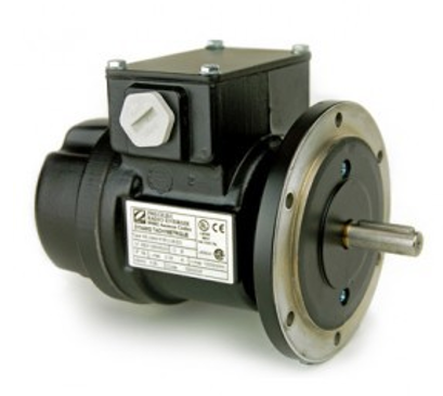
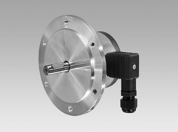
Tachogenerator
-
Principle: Electromechanical device that generates a voltage proportional to shaft speed.
-
Output:
-
DC Tachogenerators produce a steady DC voltage (e.g. 0–10 V) where voltage = K × RPM.
-
AC Tachogenerators output an AC waveform whose amplitude (or frequency, in some designs) varies with speed.
-
-
Feedback: Continuous analog signal that directly represents instantaneous speed.
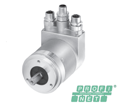
Encoder
-
Principle: Optical or magnetic sensor that counts discrete pulses as a shaft rotates.
-
Types:
-
Incremental Encoders emit N pulses per revolution; speed is derived by measuring pulse frequency.
-
Absolute Encoders provide a unique digital code for each angular position, giving both speed and position.
-
-
Output: Digital pulse train (e.g. TTL, HTL) or serial/parallel word (absolute).
2. Key Comparison Criteria
| Criterion | Tachogenerator | Encoder |
|---|---|---|
| Signal Type | Continuous analog voltage or AC waveform | Digital pulses or position words |
| Resolution | Limited by sensitivity (≈0.01 V/RPM) | Very high (up to 65,536 PPR or more) |
| Speed Range | Broad linear range from near zero to high RPM | Limited by maximum encoder frequency |
| Latency | Immediate (no sampling delay) | Depends on pulse counting interval |
| Environmental Robustness | Very rugged; tolerates dust, moisture, vibration | Sensitive optics/magnets; requires clean mounts |
| Signal Processing | May require filtering or voltage scaling | Requires pulse-counting electronics or encoder interface |
| Maintenance | Brush wear in brushed models; brushless options available | Minimal moving parts, but optics need cleaning |
| Cost | Moderate; simple design | Ranges from low-cost incremental to higher-cost absolute |
| Position Feedback | Speed only | Speed (incremental) and often absolute position |
3. When to Choose a Tachogenerator
-
Harsh Environments
-
Enclosures with dust, oil mist, wash-downs, or heavy vibration.
-
IP65+ housings and brushless designs ensure long life with minimal maintenance.
-
-
Analog Control Systems
-
Existing drives or PLC analog inputs that accept 0–10 V or 4–20 mA.
-
Simplifies wiring by avoiding digital pulse interfaces.
-
-
High Dynamic Response
-
Immediate, continuous signal is ideal for very fast load changes in PID loops.
-
No quantization delay as with pulse counts.
-
-
Cost-Sensitive Speed-Only Applications
-
Where absolute position isn’t needed and resolution requirements are modest (±1 RPM, for example).
-
4. When to Choose an Encoder
-
High Resolution & Precision
-
Incremental encoders offering thousands of pulses per revolution (PPR) for fine speed measurement.
-
Absolute encoders for multi-turn position tracking plus speed.
-
-
Digital Control Architectures
-
Modern servo drives and motion controllers with high-speed quadrature inputs.
-
Direct integration into fieldbus or EtherCAT networks (with absolute encoders).
-
-
Position-Dependent Processes
-
CNC machining, robotics, or indexing tables where knowing the exact shaft angle is as important as speed.
-
-
Diagnostics & Advanced Features
-
Many encoders include built-in diagnostics (e.g., signal strength, temperature) and multi-turn counters.
-
5. Hybrid Approaches
In some demanding applications, a combined solution yields the best of both worlds:
-
Tacho + Incremental Encoder: Use the tacho’s smooth analog feedback for fast loop response, and the encoder for startup homing and position tasks.
-
Encoder with Velocity Filter: Implement hardware or software filtering to produce a quasi-analog velocity signal derived from encoder pulses.
6. Practical Selection Tips
-
Match Signal Levels: Confirm your controller’s input ranges (0–10 V, ±10 V, 4–20 mA, 5 V TTL, etc.) and select sensors accordingly.
-
Check Mechanical Fit: Verify shaft diameters, mounting flanges, and coupling types to avoid custom adapters.
-
Evaluate Maintenance Needs: Brushless tacho and sealed encoders reduce service intervals.
-
Consider Total Cost of Ownership: Factor in not only purchase price but installation complexity, spare-parts availability, and downtime risk.
Conclusion
Both tachogenerators and rotary encoders are proven speed-sensing technologies with distinct advantages. Choose a tachogenerator when you need rugged, low-latency analog feedback for speed-only control in harsh environments. Opt for an encoder when high resolution, position awareness, and deep digital integration are paramount. And for the most demanding systems, consider a hybrid approach that leverages the strengths of both devices. By aligning sensor capabilities with your application’s performance, environmental, and budgetary requirements, you’ll ensure reliable, precise speed control that keeps your machinery—and your processes—running at peak efficiency.